Forced Tunneling for Site-to-Site VPN (Default Site)
Securing your on-premises network connection to Azure is key. By default, Azure sends outbound traffic directly through its gateways. But what if you need to route and inspect that traffic through your on-premises security devices? In this guide, I'll show you how to set up a Site-to-Site VPN and configure Forced Tunneling in Azure.
Let's dive in.
On-premises Setup
- PowerShell in version 7.4.5 with Azure PowerShell module in version 12.3.0
- Mikrotik hAP ac³ in version 7.9 (stable) - Initiator
- On-premises Networks:
- 192.168.1.1/32
- 192.168.88.0/24
- 192.168.100.0/24
- 10.200.9.0/24
- 10.200.10.0/24
- 10.200.15.0/24
- 10.200.16.0/24
- On-premises Networks:
Azure Setup
On the Azure side, we'll create the following resources to establish the VPN connection:
- Virtual Network: With the address space (10.100.0.0/16)
- Local Network Gateway: Represents the on-premises VPN device in Azure.
- Virtual Network Gateway: Acts as the VPN gateway for the Azure virtual network.
- VPN Connection: Configured with a custom IPSec policy - Responder
1. Create Tags for All Resources
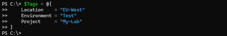
To improve cost tracking and resource management, we'll start by creating tags for all Azure resources. Use the following PowerShell script::
$Tags = @{
    Location    = "EU-West"
    Environment = "Test"
    Project     = "My-Lab"
}
2. Create a Resource Group
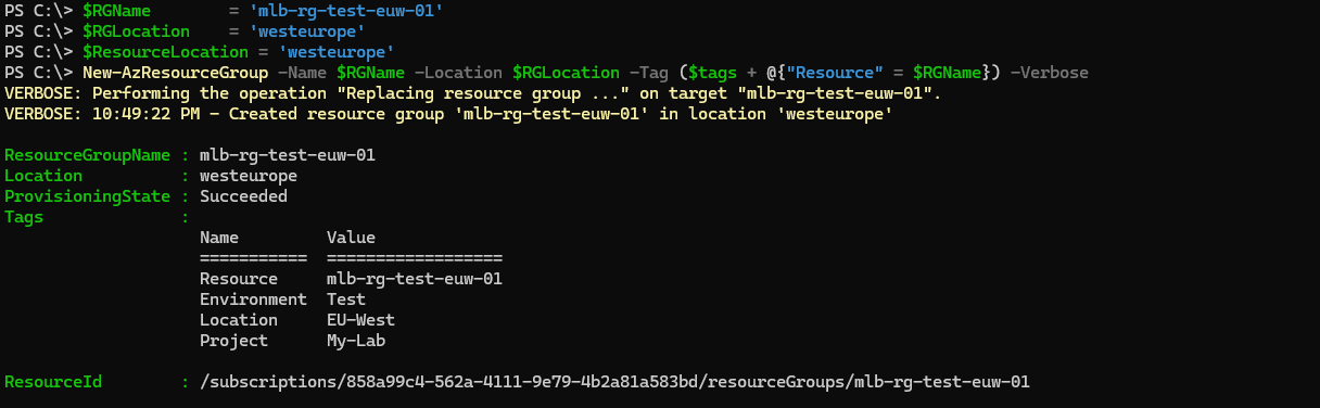
Every single resource in Azure must reside within Resource group. Resource group is some logical unit/container storing metadata for resources. Azure resources and resource group can be in different region. I'm using EU-West region. Let's create one: :
$RGName        = 'mlb-rg-test-euw-01'
$RGLocation    = 'westeurope'
$ResourceLocation = 'westeurope'
New-AzResourceGroup -Name $RGName -Location $RGLocation -Tag ($tags + @{"Resource" = $RGName}) -Verbose
3. Create Network Security Groups (NSGs)
Create Network Security Groups (NSGs) to control network access. Not strictly necessary, but I'll create them for demonstration. For simplicity, I will leave NSGs with default inbound and outbound settings:
$NSGName1      = 'mlb-nsg-test-euw-01'
$NSGName2      = 'mlb-nsg-test-euw-02'
$NSGSubnet1 = New-AzNetworkSecurityGroup -ResourceGroupName $RGName -Location $ResourceLocation -Name $NSGName1 -Tag ($tags + @{"Resource" = $NSGName1}) -Verbose
$NSGSubnet2 = New-AzNetworkSecurityGroup -ResourceGroupName $RGName -Location $ResourceLocation -Name $NSGName2 -Tag ($tags + @{"Resource" = $NSGName2}) -Verbose

4. Prepare Subnets for the Azure VNet
Next, we'll prepare the subnets for the Azure Virtual Network (VNet) and associate the previously created Network Security Groups (NSGs). Note that NSGs cannot be attached to the Gateway subnet, as this would block essential traffic required for the VPN Gateway to function.
For the VNet, we'll use the address space 10.100.0.0/16 (which we'll define in the next step). Within this address space, we'll create the following subnets:
- Subnet 1:
10.100.9.0/24 - Subnet 2:
10.100.10.0/24 - GatewaySubnet:
10.100.1.0/24
The GatewaySubnet requires special attention. While the smallest supported prefix is /27 (providing 32 IP addresses), the Azure VPN Gateway needs at least 8 IP addresses to operate. For better scalability, I've chosen a /24 prefix, which provides 256 IP addresses.
Important Considerations:
- Ensure that the IP address ranges in Azure do not overlap with the IP addresses in your on-premises network. For example, if both networks use
10.100.0.0/16, routing issues will occur when the Site-to-Site VPN is established. Plan your subnets carefully to avoid conflicts. - The GatewaySubnet must be named exactly
GatewaySubnet(case-insensitive). Azure uses this name to identify the subnet where the VPN Gateway will be deployed.
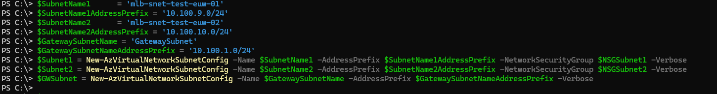
$SubnetName1      = 'mlb-snet-test-euw-01'
$SubnetName1AddressPrefix = '10.100.9.0/24'
$SubnetName2      = 'mlb-snet-test-euw-02'
$SubnetName2AddressPrefix = '10.100.10.0/24'
$GatewaySubnetName = 'GatewaySubnet'
$GatewaySubnetNameAddressPrefix = '10.100.1.0/24'
$Subnet1 = New-AzVirtualNetworkSubnetConfig -Name $SubnetName1 -AddressPrefix $SubnetName1AddressPrefix -NetworkSecurityGroup $NSGSubnet1 -Verbose
$Subnet2 = New-AzVirtualNetworkSubnetConfig -Name $SubnetName2 -AddressPrefix $SubnetName2AddressPrefix -NetworkSecurityGroup $NSGSubnet2 -Verbose
$GWSubnet = New-AzVirtualNetworkSubnetConfig -Name $GatewaySubnetName -AddressPrefix $GatewaySubnetNameAddressPrefix -Verbose
5. Create Virtual Network
In this step, we'll create the Virtual Network (VNet) in Azure. The VNet will use the address space 10.100.0.0/16, which must include all the subnets created in the previous step:
10.100.9.0/2410.100.10.0/2410.100.1.0/24(GatewaySubnet)
Important Considerations:
- The VNet's address space must not overlap with your on-premises network. For example, if your on-premises network uses
10.100.0.0/16, you'll need to choose a different address space for the Azure VNet to avoid routing conflicts. - Ensure that the subnets created earlier fall within the VNet's address space. This is critical for proper network communication and VPN connectivity.
$VNETName      = 'mlb-vnet-test-euw-01'
$VNETAddressPrefix = '10.100.0.0/16'
$VNET = New-AzVirtualNetwork -Name $VNETName -ResourceGroupName $RGName -Location $ResourceLocation -AddressPrefix $VNETAddressPrefix -Subnet $Subnet1,$Subnet2,$GWSubnet -Tag ($tags + @{"Resource" = $VNETName}) -Verbose

6. Create Local Network Gateway (LNGW)
To establish a Site-to-Site VPN connection, we need to create a Local Network Gateway (LNGW) in Azure. The LNGW represents your on-premises VPN device (in this case, a MikroTik router) within Azure.
There are two mandatory parameters for configuring the LNGW:
- Endpoint: This is the public IP address or Fully Qualified Domain Name (FQDN) of your on-premises VPN device. Azure uses this endpoint to establish communication with your on-premises network.
- Address Prefixes: These are the IP address ranges of your on-premises network. Azure uses these prefixes to determine which traffic should be routed through the Site-to-Site VPN connection.
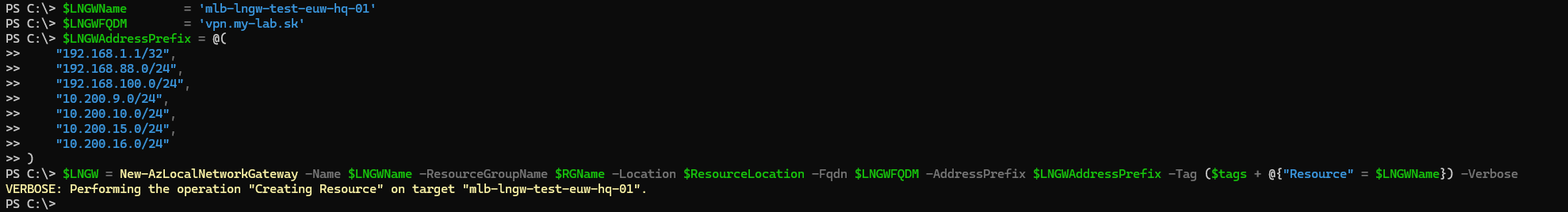
$LNGWName        = 'mlb-lngw-test-euw-hq-01'
$LNGWFQDM        = 'vpn.my-lab.sk'
$LNGWAddressPrefix = @(
    "192.168.1.1/32",
    "192.168.88.0/24",
    "192.168.100.0/24",
    "10.200.9.0/24",
    "10.200.10.0/24",
    "10.200.15.0/24",
    "10.200.16.0/24"
)
$LNGW = New-AzLocalNetworkGateway -Name $LNGWName -ResourceGroupName $RGName -Location $ResourceLocation -Fqdn $LNGWFQDM -AddressPrefix $LNGWAddressPrefix -Tag ($tags + @{"Resource" = $LNGWName}) -Verbose
7. Create Public IP Address (PIP)
To establish a connection between Azure and your on-premises network, we need a Public IP address (PIP). This address must be routable on the internet, allowing communication between your on-premises network and Azure, and vice versa.
In the next step, we'll create a Virtual Network Gateway (VNGW) with a Standard SKU. To ensure compatibility, the Public IP address must also use the Standard SKU.
Ensure the Public IP address and the Virtual Network Gateway use the same SKU (Standard) to avoid compatibility issues:
$PIPName         = 'mlb-pip-test-euw-01'
$IPAllocation    = 'Static'
$VNGWPIP = New-AzPublicIpAddress -Name $PIPName -ResourceGroupName $RGName -Location $ResourceLocation -AllocationMethod $IPAllocation -Tag ($tags + @{"Resource" = $PIPName}) -Verbose

8. Create Virtual Network Gateway (VNGW)
With all the prerequisites in place, we can now proceed to create the Virtual Network Gateway (VNGW). The VNGW is an Azure resource that acts as the entry point for network traffic, enabling connectivity between your Azure Virtual Network (VNet) and other networks.
When creating the VNGW, several key parameters must be configured:
- VPN SKU: Choose the SKU based on your network throughput/performance.
- Generation: This determines the underlying hardware and features available.
- Active-Active Mode: If high availability is required. This configuration requires two public IP addresses.
- VPN Type:
RouteBased(dynamic routing) orPolicyBased(static routing).
$VNGWName        = 'mlb-vngw-test-euw-hq-01'
$VNGWSKU         = 'VpnGw1'
$VpnGatewayGeneration = 'Generation1'
$GatewayType    = 'Vpn'
$VpnType        = 'RouteBased'
$AzVirtualNetworkGatewayIpConfigName = 'VNGWIPConfig'
$Subnet = Get-AzVirtualNetworkSubnetConfig -Name $GatewaySubnetName -VirtualNetwork $VNET
$GWIPConfig = New-AzVirtualNetworkGatewayIpConfig -Name $AzVirtualNetworkGatewayIpConfigName -SubnetId $Subnet.Id -PublicIpAddressId $VNGWPIP.Id -Verbose
$VNGW = New-AzVirtualNetworkGateway -Name $VNGWName -ResourceGroupName $RGName -Location $ResourceLocation -IpConfigurations $GWIPConfig -GatewayType $GatewayType -VpnType $VpnType -GatewaySku $VNGWSKU -VpnGatewayGeneration $VpnGatewayGeneration -Tag ($tags + @{"Resource" = $VNGWName}) -Verbose

9. Configure IPSec Policy
Once the Virtual Network Gateway (VNGW) is deployed, we can configure the IPSec policy for the VPN connection. While Azure provides default settings (which you can find here), it's important to verify that your on-premises VPN device supports the chosen encryption and hashing algorithms. For this demonstration, I'll customize the policy to meet specific requirements.
IPSec operates in two phases:
- Phase 1: Key Exchange (IKE - Internet Key Exchange)
- This phase establishes a secure and authenticated channel between the Azure VPN Gateway and the on-premises VPN device.
- It uses mutual authentication, typically through a pre-shared key or certificates.
- Phase 2: IPSec
- This phase handles the encryption of data transmitted between the two endpoints.
- It ensures that all traffic passing through the VPN tunnel is secure and private.
For this setup, I'll configure the following parameters:
- IKE Encryption:
AES256 - IKE Integrity:
SHA256 - DH Group:
DHGroup2048 - IPSec Encryption:
AES256 - IPSec Integrity:
SHA256 - PFS Group:
PFS24 - SA Lifetime:
3600 seconds - SA Data Size:
512000 KB
Let's create a custom IPSec policy:
$IkeEncryption        = 'AES256'
$IkeIntegrity         = 'SHA256'
$DhGroup              = 'DHGroup2048'
$IpsecEncryption      = 'AES256'
$IpsecIntegrity       = 'SHA256'
$PfsGroup             = 'PFS24'
$SADataSizeKilobytes  = '512000'
$SALifeTimeSeconds    = '3600'
$IPSecPolicy = New-AzIpsecPolicy -IkeEncryption $IkeEncryption -IkeIntegrity $IkeIntegrity -DhGroup $DhGroup -IpsecEncryption $IpsecEncryption -IpsecIntegrity $IpsecIntegrity -PfsGroup $PfsGroup -SADataSizeKilobytes $SADataSizeKilobytes -SALifeTimeSeconds $SALifeTimeSeconds -Verbose

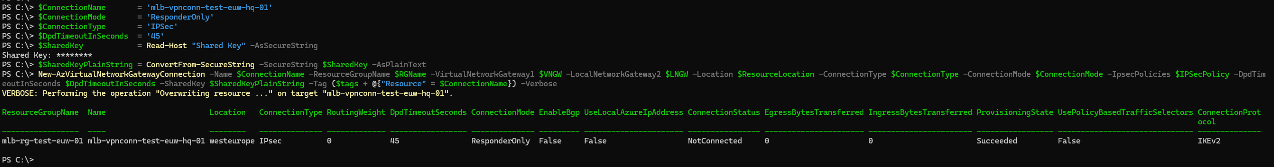
10. Create VPN Connection
With both the Local Network Gateway (LNGW) and Virtual Network Gateway (VNGW) provisioned, we can now create the VPN connection. For this configuration, I'll set the connection to operate in ResponderOnly mode, meaning the connection will be initialized from the on-premises device (MikroTik). If you prefer Azure to act as the initiator, you can adjust the mode accordingly.
To secure the VPN connection, we'll set a pre-shared key for IKE Phase 1 authentication. The -SharedKey parameter expects a plain text string, so we cannot use a secure string here. Important: Remember this key, as
it will be required when configuring the on-premises VPN device.
$ConnectionName       = 'mlb-vpnconn-test-euw-hq-01'
$ConnectionMode       = 'ResponderOnly'
$ConnectionType       = 'IPSec'
$DpdTimeoutInSeconds  = '45'
$SharedKey            = Read-Host "Shared Key" -AsSecureString
$SharedKeyPlainString = ConvertFrom-SecureString -SecureString $SharedKey -AsPlainText
New-AzVirtualNetworkGatewayConnection -Name $ConnectionName -ResourceGroupName $RGName -VirtualNetworkGateway1 $VNGW -LocalNetworkGateway2 $LNGW -Location $ResourceLocation -ConnectionType $ConnectionType -ConnectionMode $ConnectionMode -IpsecPolicies $IPSecPolicy -DpdTimeoutInSeconds $DpdTimeoutInSeconds -SharedKey $SharedKeyPlainString -Tag ($tags + @{"Resource" = $ConnectionName}) -Verbose
11. Enable Forced Tunneling
In this final step, we'll configure forced tunneling for the Site-to-Site VPN. As mentioned earlier, this configuration cannot be done through the Azure portal and requires PowerShell or CLI.
Forced tunneling ensures that all internet-bound traffic from your Azure Virtual Network (VNet) is routed through the VPN tunnel to your on-premises network. This allows you to inspect and filter internet traffic using your on-premises security devices, ensuring compliance with organizational policies.
Set-AzVirtualNetworkGatewayDefaultSite -GatewayDefaultSite $LNGW -VirtualNetworkGateway $VNGW -Verbose

At this point, all internet-bound traffic is configured to be force-tunneled through the on-premises gateway. Ensure that your on-premises VPN device is configured with 0.0.0.0/0 as the traffic selector to match this setup.
12. Configure on-prem device Mikrotik for IKEv2/IPSec and inicialize connection
With the Azure configuration complete, let's configure the on-premises VPN device. In this case, we're using a MikroTik router. Since we've defined a strict IPsec policy, the MikroTik configuration must match these settings. Otherwise, IKE Phase
1 or IPSec Phase 2 will fail, and the VPN tunnel won't initialize.
Let's proceed with configuring MikroTik and sending the initial contact:
# Create profile for IKEv2 (Phase 1):
/ip/ipsec/profile/add name="vpn-azure-p1-profile" hash-algorithm=sha256 prf-algorithm=sha256 enc-algorithm=aes-256 dh-group=modp2048 proposal-check=obey lifetime=1h lifebytes=512000k nat-traversal=no dpd-interval=45 dpd-maximum-failures=5
# Create Peer (Phase 1)
/ip/ipsec/peer/add name=vpn-azure-peer address=51.144.32.222 port=500 local-address=188.167.102.81 profile=vpn-azure-p1-profile exchange-mode=ike2 passive=no send-initial-contact=yes
# Create Identity (Phase 1)
/ip/ipsec/identity/add peer=vpn-azure-peer auth-method=pre-shared-key secret=Heslo12345 my-id=fqdn:vpn.my-lab.sk remote-id=address:51.144.32.222 match-by=remote-id mode-config=none generate-policy=no
# Create Proposal for IPSec (Phase 2)
/ip/ipsec/proposal/add name=vpn-azure-p2-proposal auth-algorithms=sha256 enc-algorithms=aes-256-cbc lifetime=1h pfs-group=modp2048
# Create IPSec policy (Phase 1 and Phase 2) - 0.0.0.0/0 as traffic selector
/ip/ipsec/policy/add peer=vpn-azure-peer tunnel=yes src-address=0.0.0.0/0 src-port=any dst-address=10.100.0.0/16 dst-port=any action=encrypt level=require ipsec-protocols=esp proposal=vpn-azure-p2-proposal 
12. Connection check
Now that the VPN connection has been initialized, let's verify the status of the peers. On both sides (Azure and on-premises), we should see a connection status of Established or Connected.
Let' start with Mikrotik router as initiator
# Check conection Active peers:
/ip/ipsec/active-peers/print

Next, we'll verify the connection status on the Azure side using PowerShell:
Get-AzVirtualNetworkGatewayConnection -ResourceGroupName $RGName -Name $ConnectionName

As we can see, the connection has been securely initialized and established.
With the connection successfully established, you can now securely route traffic between Azure and your on-premises environment.
13. Few key points to keep in mind
Before concluding, here are a few key points to keep in mind:
1. Asymmetric Routing
Asymmetric routing is not allowed in this setup. For example, if you place an Azure VM in a subnet and attempt to access it directly from the internet, it will not work. This is because forced tunneling routes all traffic (including internet-bound traffic) through the VPN gateway. To establish such a connection, you would need to create a custom route to bypass the forced tunneling configuration.
2. VNet Peering
VNet peering is fully supported in this setup. You can peer multiple Azure Virtual Networks (VNets) and route traffic through the VPN gateway. This eliminates the need to create a separate GatewaySubnet and VPN connection for each
VNet.
3. Troubleshooting VPN Connection Issues
If your VPN connection fails to establish, follow these steps to diagnose and resolve the issue:
- On-premises Device: Enable IPSec logging to identify the root cause of the problem. For MikroTik, use the following command:
Check the logs to determine which phase (IKE Phase 1 or IPSec Phase 2) is failing and verify that the configuration matches on both sides./system/logging/add prefix=ipsec topics=ipsec - Azure Side: Use the Azure VPN troubleshooting tool to diagnose the issue. Go to the VPN gateway in the Azure portal, select Troubleshoot, and choose or create a storage account to store the VPN logs. Download
the logs and analyze them to identify issues such as mismatched IPSec policies, incorrect pre-shared keys, or other configuration errors.
Here's an example of a log entry indicating a failure during the IKE negotiation process (pre-shared key):
IKEv2-S2S [ICookie] 0xB968C77D390F5ACC [RCookie] 0x30AE204D0842D1A7 [TunnelId] 0x0 [IkeEvent] SA_NEGOTIATION_FAILED
For [SA_type] MM_SA [SAEstablished] false [SA_CREATION_DIRECTION] Inbound [FailureDirection] Outbound
[ErrorCode] 0x3602 [ErrorMessage] Failed to verify signature.
Add a Comment